Clamp/Flange Flue gas valve is the core control equipment of industrial flue gas treatment system, which is widely used in thermal power generation, iron and steel metallurgy, petrochemical industry, waste incineration, cement manufacturing and other fields. Its main functions include flow regulation, media isolation, pressure balance, system protection, and it is suitable for complex working conditions of high temperature, high dust, and strong corrosion (e.g. SO₂, HCl, Cl-, etc.).
Core Role
Safeguard the safe operation of flue gas systems, e.g. preventing explosions caused by flue gas backflow.
Regulate flue gas flow and pressure to optimise the efficiency of environmental protection equipment such as desulphurisation towers and dust collectors.
Isolate equipment for easy maintenance and reduce the risk of downtime.
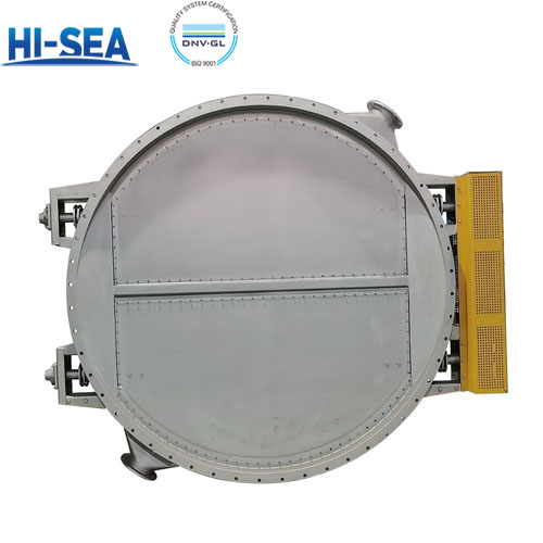
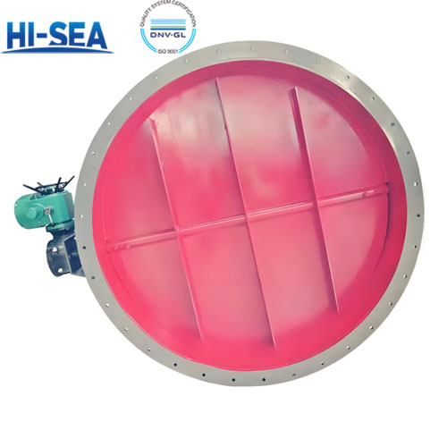
Structural components
Valve body: flow channel design is optimised to reduce the accumulation of dust and abrasion, and the material should be high temperature resistant and corrosion resistant.
Valve plate: Butterfly valve plate often adopts eccentric structure to reduce abrasion. Surface hardening treatment to improve wear resistance.
Sealing components: high temperature sealing materials such as graphite, metal wound gaskets, fluorine rubber. Double seal design (main seal + service seal) to enhance reliability.
Driving device: Multi-type adaptable, high-precision transmission. Electric actuators need to be explosion-proof and high temperature resistant. Pneumatic actuators are equipped with filtering and pressure reducing valves to prevent dust clogging.
Advantages
Efficient smoke evacuation: The smoke valve can be opened quickly when a fire occurs, effectively removing smoke.
Safe and reliable: the smoke valve can be interlocked with the fire detector to automatically activate the smoke evacuation function, ensuring the timely elimination of smoke in the early stage of fire.
Flexible operation: the smoke exhaust valve can be operated manually or electrically, adapting to different use scenarios and needs.
Strong durability: Adopting high-quality materials and advanced manufacturing process, it has good wear-resistant, corrosion-resistant and high temperature-resistant performance, and can operate stably for a long time.
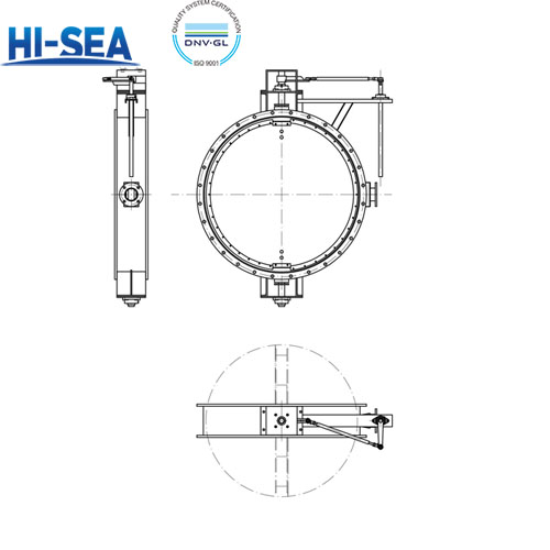
Parameter
Nominal diameter: DN50 ~ 3000
Nominal pressure: 6 ~ 40 (corresponding to ANSI 150 ~ 2500)
Applicable temperature: -40℃ ~ +800℃ (according to material and design)
Valve body material: carbon steel, stainless steel, duplex steel, Hastelloy, fluorine lining / ceramic
Connection: flanged, clamped, welded
Driving mode: manual, electric, pneumatic, electro-hydraulic linkage
Size chart
| Name |
Diameter DN |
PS MAX(bar) |
Intφ |
Thicknesses
D |
B |
CH |
H |
E |
E1 |
Weights KG |
| ISO5210 |
Flange |
Clamp |
| Flange/Clamp |
150 |
3 |
160 |
140 |
470 |
14 |
17 |
F07 |
F05 |
16 |
13 |
| 200 |
3 |
211 |
140 |
495 |
14 |
17 |
F07 |
F05 |
19 |
15 |
| 250 |
2 |
265 |
140 |
522 |
14 |
17 |
F07 |
F05 |
23 |
18 |
| 300 |
2 |
316 |
140 |
547 |
14 |
17 |
F07 |
F05 |
26 |
21 |
| 350 |
2 |
350 |
140 |
564 |
14 |
17 |
F07 |
F05 |
33 |
26 |
| 400 |
2 |
400 |
140 |
588 |
14 |
17 |
F07 |
F05 |
37 |
29 |
| 450 |
1 |
450 |
190 |
648 |
22 |
20 |
F10 |
F07 |
49 |
39 |
| 500 |
1 |
500 |
190 |
673 |
22 |
20 |
F10 |
F07 |
61 |
49 |
| 600 |
1 |
600 |
190 |
721 |
22 |
20 |
F10 |
F07 |
74 |
56 |
| 700 |
1 |
700 |
190 |
771 |
22 |
20 |
F10 |
F07 |
85 |
64 |
| 800 |
0.5 |
800 |
190 |
821 |
22 |
20 |
F10 |
F07 |
112 |
85 |
| 900 |
0.5 |
900 |
240 |
963 |
27 |
25 |
F14 |
F12 |
134 |
|
| 1000 |
0.5 |
1000 |
240 |
1013 |
27 |
25 |
F14 |
F12 |
147 |
|
| 1100 |
0.5 |
1100 |
240 |
1063 |
27 |
25 |
F14 |
F12 |
160 |
|
| 1200 |
0.5 |
1200 |
240 |
1113 |
27 |
25 |
F14 |
F12 |
191 |
|
| 1300 |
0.2 |
1300 |
240 |
1163 |
27 |
25 |
F14 |
F12 |
226 |
|
| 1400 |
0.2 |
1400 |
240 |
1215 |
27 |
25 |
F14 |
F12 |
265 |
|
| 1500 |
0.2 |
1500 |
240 |
1265 |
27 |
25 |
F14 |
F12 |
335 |
|
Product Show